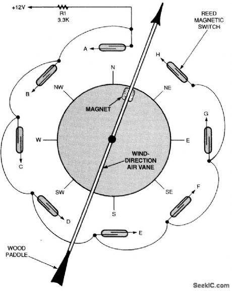
DIY Anemometer Wind Speed Sensor Device Circuit Diagram So, some will measure the speed by counting the number of rotations of the cups while other will generate certain voltage proportional to the speed of the wind. Adafruit Anemometer: It is a Rotating cup Anemometer which is based on hall effect principle and contain a hall effect sensor which generates analog voltage when the cups rotate. By
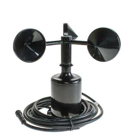
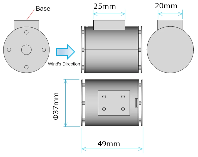
Today in this tutorial we will make a Wind Speed Meter Using Anemometer & Arduino and display the wind speed on 0.96 inch OLED Display in m/s. The NPN pulse output Anemometer sensor is a 3 cup type Anemometer that is capable of measuring wind speed up to 70-meter per seconds or 156 mph. It is composed of a shell, the wind cup, and the
How to Measure Wind Speed using Anemometer & Arduino Circuit Diagram
The sensor can measure wind speed ranging from 0 to 40 m/s and wind direction from 0 to 360 After assembling the sensor as per the circuit diagram above, lets move to the coding part of this project. According to the above table the inquiry frame for getting the Sensor reading hexadecimal is as follows: 1. Introduction: Using an Anemometer and Arduino to Measure Wind Speed. By ForceTronics ForceTronics Store Follow. More by the author: In this Instructable we look at how to measure wind speed using an anemometer and Arduino. This approach will work on both ARM and AVR based Arduinos.

The anemometer sensor we are using here is the Adafruit anemometer. The Adafruit anemometer is capable of measuring wind speeds up to 70 m/s or 156 mph which should be adequate for our location. We can interface the Adafruit Anemometer Sensor with Arduino and OLED Display. The sensor will measure the wind speed in m/s and displays the value on OLED Screen.
ElectroSchematics.com Circuit Diagram
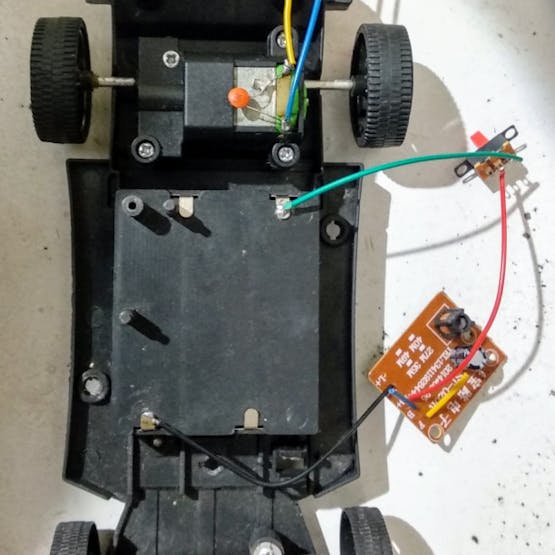
Use the 3 different colored wires to connect the sensor module. Insert the Hall module and point the sensor facing the magnet at a distance of 2 to 4 mm. Test if the rotation of the shaft does not hit the magnet with the sensor. Use a 3.7 V battery to test if the module responds to the approach of the magnet by turning the led to each contact. Use an anemometer with the Arduino board to measure wind speed. Power and connect the sensor to the Arduino and write a simple code to get wind speed values in different units. Wiring the Circuit: Arduino with Anemometer.